
|
|
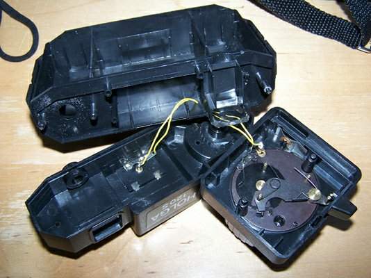
opening the camera - note how the flash wires are routed from the shutter mechanism through the camera body and up into the top, to the flash shoe
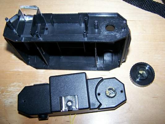
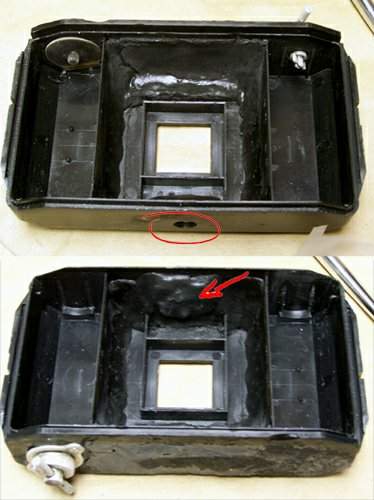
this is what the top of the body looks like - i'll be discarding the original top, removing nearly all the extraneous plastic, then filling the top of the body with epoxy
note the well above the lens area - a pointless cavity which will be removed as well
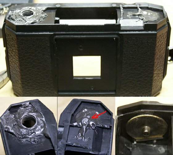
the left panel shows the winding hole filled-in and leveled off
the red arrow points to a partly-visible screw head, mostly embedded in epoxy, which holds the new metal 120 spool pin in place (as seen in the right panel)
these metal pieces provide spool tension - they are epoxied and screwed in place
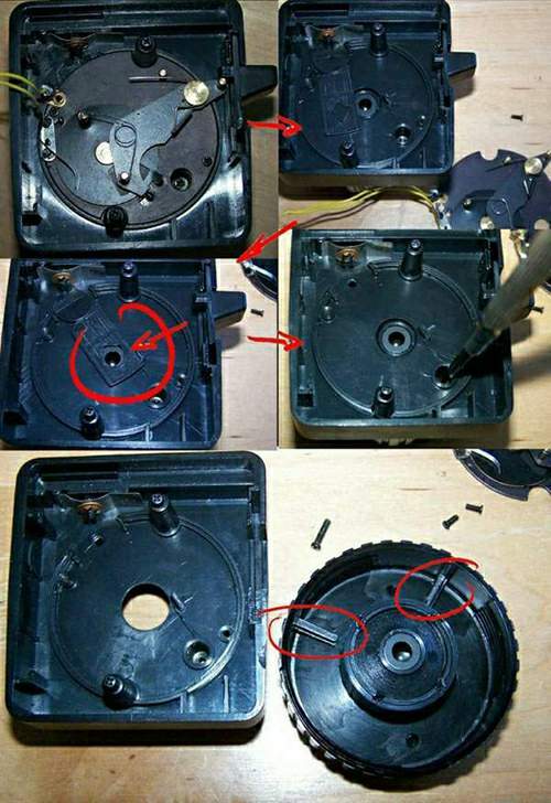
panel one shows the shutter assembly in place, panel two shows it removed
panel three shows the useless aperture (removed and discarded) which all Holga modification web pages drone on about
panel four shows the screw which holds the lens in place being removed (we'll need to know about this in a minute) - the lens assembly is then unscrewed and laid face down
panel five, looking inside the lens focusing ring, indicates the positions of the stops against which the retaining screw (removed in panel four) impacts
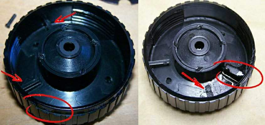
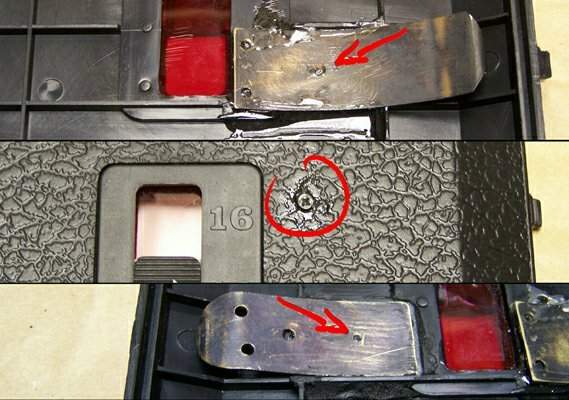
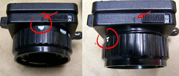
panel one : the two arrows show the original positions of the stops - note the circled icon on the outer surface of the focusing ring for future reference
panel two : the arrow shows the original position of the removed tab, and the circle shows the newly positioned stop tab
this step provides a much closer focusing setting (you'll see the difference below)
this illustrates the addition of a tripod nut and the application of an ample supply of epoxy which provides a good deal of weight, and makes the camera body much stronger. the top and bottom are filled-in here, the sides will be more completely filled-in later
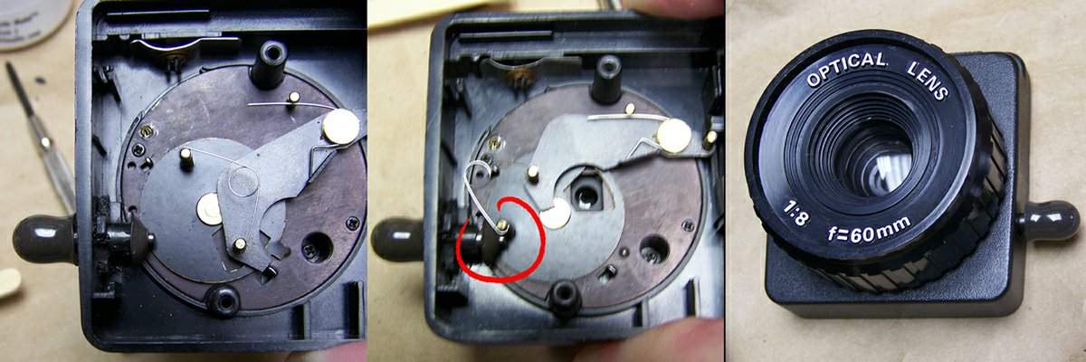
in this step the Bulb (''B'') setting is added : the metal shaft slides through a plastic flange, superglued to the side of the lens base
when the shaft is pushed in, the end of the shaft stops the shutter mechanism until the shutter is released
the third panel shows the epoxy knob which has been added to the outside of the shaft ... how sexy !
here you can see the extremes - how far the modified focusing ring can now be turned
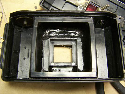
here the bottom is filled-in flat around the tripod nut, and the film transport piece is returned (the four sides of which had been completely removed) and epoxied more fully in place. the sides are also filled-in which helps stop light leaks, adds strength and weight, and also fixes the plate firmly in place
currently i'm working on the clasps which hold the damn thing closed (when all goes well)